
- HOME >
- Motorized Stages Guide >
- Accuracy Verification
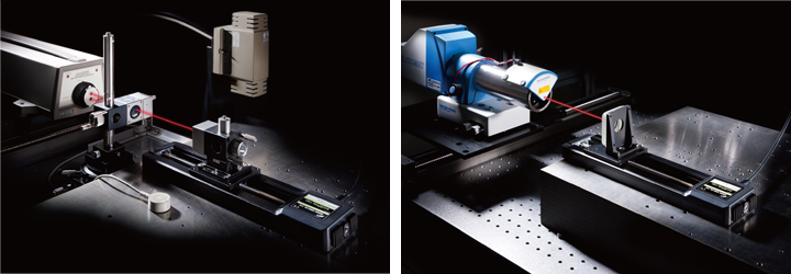
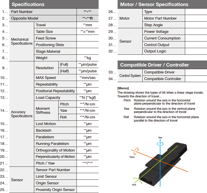
- Measurement of Linear Stage Accuracy
- Measurement of Rotation Stage Accuracy
- Measurement of Goniometer Stage Accuracy
- Accuracy Verification
- Stepping Motors Guide
- Linear / Rotation / Goniometer
- GS/CS series Guide
- SGMV series Translation Motorized Stages AC servo Motor
- Vacuum Compatible Motorized Stage Guide
- Controllers
- Piezo Guide
- Drivers

In addition, all measuring instruments are traceable standard instruments compliant to the national standard.
| Category | Measurement Item | Device Used | Standards | JP Yen |
| Linear Stage | Positioning Accuracy | Dynamic Calibrator | JIS B 6190 | 50,000 |
| Positional Repeatability | ||||
| Lost Motion | ||||
| Running Parallelism | Dial Indicator | Company Standard | 30,000 | |
| Pitch/Yaw | Auto Collimator | Company Standard | 30,000 |
It has to be guaranteed that measured values and indicated values are within the specification range of international standard values. In other words, traceability must be ensured. JIS defined this traceability as “the capacity to trace measurement results back to the domestic measurement standards, with the use of measuring instruments that have gone through a sequence of calibrations with high-ranking standards.”
| Category | Measurement Item | Device Used | Standards | JP Yen |
| Rotation Stage | Positional Repeatability | Rotary Encoder | Company Standard | 30,000 |
| Lost Motion | ||||
| Wobble Accuracy | Dial Indicator | Company Standard | ||
| Goniometer Stage | Positional Repeatability | Rotary Encoder | Company Standard | 30,000 |
| Lost Motion | ||||
| Rotation Center Height | Three Dimensional Instrumentation | Company Standard | 30,000 | |
| Rotation Center Deviation Accuracy |
We check accuracy of motorized stages as a single unit.
Regarding the accuracy check in assembled state, we need to confirm use conditions etc. Contact our International Sales Division separately.
We cannot conduct accuracy check at delivery destinations.
We will request a check from organizations such as Japan Quality Assurance Organization as necessary.
Contact our International Sales Division separately for more information.
* Precision ground screws
* Crossed roller guide
Refer to the accuracy verification page for more information.
(Half)
Travel per pulse for half step
Pitch
Yaw
Roll
It indicates the degree of tilt of the table top (″) when 1N load is exerted at the position 1cm away from the center of the stage surface
Stiffness in the direction of tilt around the axis in the horizontal plane perpendicular to the direction of travel when moving the stage for full travel.
Stiffness in the direction of tilt around the axis in the vertical plane perpendicular to the direction of travel when moving the stage for full travel.
Stiffness in the direction of tilt around the axis in the horizontal plane parallel to the direction of travel when moving the stage for full travel.
* Note that it is different from “Running Parallelism”.
Yaw
Maximum angle displacement in the direction of tilt around the axis in the vertical plane perpendicular to the direction of travel when moving the stage for full travel.
30
31
32
Current Consumption
Control Output
Output Logic
Specifications of the sensor.
35
Compatible Controller