- HOME >
- Manual Stages Guide >
- Goniometer Stages Guide

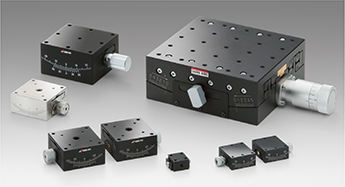
Goniometers are rotation stages that rotate
about an axis that is located at a distance above the surface of the stage.
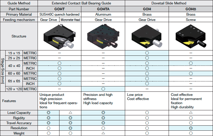
Used for direction adjustment and correction, or tilting and rotation of samples. Products with different guide mechanisms or feed mechanisms are also available.
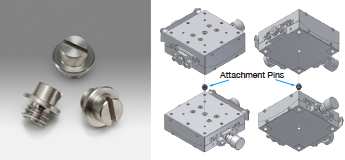
Use of attachment pins to reduce assembly adjustment time.
In case of single shipment, this product is delivered only by mail.
An αβ axis stack is easily assembly by attaching an alignment pin at the top center of a GOHT series stage, and inserting it into the hole in the lower surface of the top stage.
Ideal not only for assembly of single axis stages, but also for positioning when mounting on instruments or devices.
| Part Number | GOHT-AP-10 |
| JP Yen | 1,000 |
| Compatible Products | GOHT-40, 60 |
| Primary Material | SUS303 |
| Finish | None |
| Quantity [pieces] | 10 |
| Weight [kg] | 0.0005 |
| Add to Cart |
These products are developed based on Sigma Koki’s original processing technology.
③ High Stiffness
The four-array contact structure achieves high load capacity
and high stiffness (13 times stiffer than the V groove)
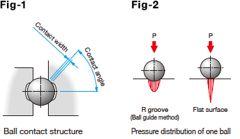
As shown in Fig-1, ball guides are machined across the arcs so that they have R groove structure and good contact with a ball allowing stable load capacity against the load in the directions where contact with the ball occurs frequently.
Long life and free of maintenance
Fig-2 shows the pressure distribution of the R groove and the flat surface.
As shown in the figure, pressure exerted on the R groove is dispersed and does not reach inside.
Thus, metal fatigue and wear are reduced.
Our original processing technology achieved an integral structure
of the main body and the guides
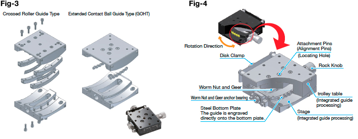
As shown in Fig-3, because the crossed roller type goniometer stage, which has been the mainstream, has the guide separate from the main body, there are many parts. Assembling a large number of parts caused errors or variation, resulting in translation errors, that is, deviation in the most important rotation center when the stage moved. Our goniometer stage as shown in Fig-4, has the guide integrated into the main body in order to compensate for assembly errors or variation by machining accuracy. With the integral structure, the displacement of the rotation center is reduced.
Rotation Center Displacement
Our ball guide goniometer stage φ0.007mm以下
Crossed roller goniometer stage manufactured
by another company
φ0.01mm以下
Reference
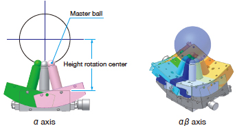
Measuring method of the displacement of rotation center.
Installing the “master ball” on the top of stage surface.
Then sequentially positioning in a certain direction from the starting point to the travel end.
Measuring by three-dimensional measuring device the position of the master ball in each position.
From the coordinate data and obtains the fluctuation width of the circular orbit, determine the center of rotation displacement amount.