- HOME >
- Manual Stages Guide >
- Definitions of Specifications and Terminology

Indicated by plus and minus using the reference position of product (when the top and bottom plates are at the same position) as the reference position. (On the outline drawing in the catalog, travel in one direction is indicated by +mm and in the opposite direction is indicated by −mm with the outline drawing position as the reference position.)
It indicates the full travel range, it the reference position can not be determined.
Extended Contact Ball Bearing Guide
Crossed roller guide
Special guide methods other than the ones listed on the left are available. Refer to the specification table of each product.
Dovetail Slide method
Leadscrew driving method
Lapping method
V groove screw
Please contact our International Sales Division if you require to use them above the ruted load capacity.
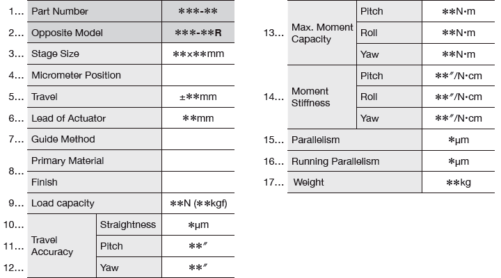
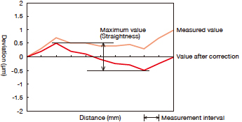
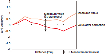
Straightness (units: µm)
travel when moving the stage for full travel.
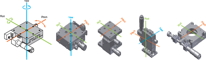
: Roll
travel when moving the stage for full travel.
Indicates the degree of tilt around the axis in the horizontal plane parallel to the direction of
travel when moving the stage for full travel.
(units: N⋅m)
(units: "/N⋅cm)
(the table center and the center of gravity of a sample does not match).
Indicates the degree of tilt of the table top (sec) when 1N load is exerted at the position 1cm away from the center of the stage surface.
[MEMO]
The drawing shows the types of tilt when a linear stage travels. Towards the direction of travel...
Move the stage and stop it at regular intervals throughout the full travel of the stage.
At each point, measure the deviation from a reference position in the horizontal plane.
The maximum deviation after correcting the deviation throughout the full travel to 0 is the straightness in the horizontal plane.
Move the stage and stop it at regular intervals throughout the full travel of the stage.
At each point, measure the deviation from a reference position in the vertical plane.
The maximum deviation after correcting the deviation throughout the full travel to 0 is the straightness in the vertical plane.
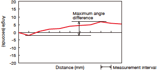
Move the stage and stop it at regular intervals throughout the full travel of the stage. At each point, measure the degree of tilt in the vertical plane. The maximum angular difference is the pitch.
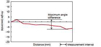
Move the stage and stop it at regular intervals throughout the full travel of the stage. At each point, measure the degree of tilt in the horizontal plane. The maximum angular difference is the yaw.
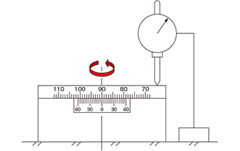
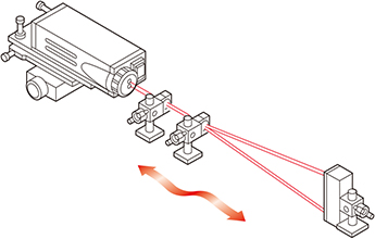
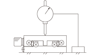
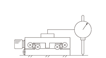
Fix a test indicator on an optical breadboard, bring it into contact with the top surface of the stage,
and measure while moving it over the whole surface of the stage.
The maximum difference of the displacement value of the test indicator is the parallelism.
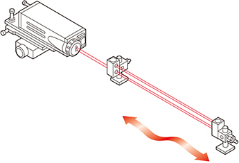
Fix a stage on an optical breadboard. Fix a test indicator on the top surface of the stage, bring it into contact with the top surface of the optical breadboard, and measure while moving the stage for the full travel. The maximum difference of the displacement value of the test indicator is the running parallelism.
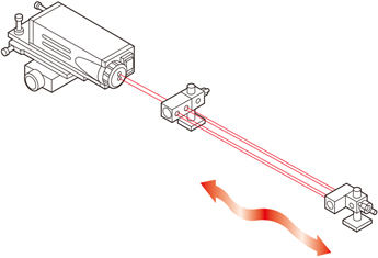
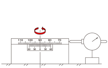
Fix a rotation stage on an optical breadboard.
Bring a test indicator into contact with the circumference of the rotation stage, and measure while turning the stage through one full rotation of 360°.
Half of the maximum difference of the displacement value of the test indicator (misalignment) is the eccentricity.
Fix a test indicator on an optical breadboard, bring it into contact with the edge of the top surface of a rotation stage,
and measure while turning the stage for through one full rotation of 360°.
The maximum difference of the displacement value of the test indicator is the wobble.